Cable Gland Strain Relief Technical Information
| Nylon | ||
| Pressure Rating: | 150 PSIG (10 BAR) Type NEMA 4x, 6 (Submersible) & 12 – IP 68 / IP 69K | |
| Materials: | Fittings: Nylon 6/6 – • V0 Rated – Flame resistant, Halogen and Phosphorous Free, Self-extinguishing, Non-toxic, Fungus resistant • Form Seal: Buna-N • Clamping Insert: Nylon • Optional O-Ring: Buna-N, FPM or Silicone • Optional Seal Ring: Polyethylene or Fiber-Reinforced Plastic |
|
| Operating Temperature: | Nylon Fittings: -40 ºF to 212 ºF (-40 ºC to 100 ºC) Nylon Fitting w/ Aluminum Clamp: -4 ºF to 158 ºF (-20 ºC to 70 ºC) |
|
| Available Colors: |
|
|
| Nickel Plated Brass | ||
| Pressure Rating: | 150 PSIG (10 BAR) Type NEMA 4x, 6 (Submersible) & 12 – IP 68 / IP 69K | |
| Materials: | • Fittings: Nickel Plated Brass • Spring (Flex Extension): 304 Stainless Steel • Form Seal: Buna-N (NBR) or FPM) • Clamping Insert: PA (Nylon) or PVDF • O-Ring: Buna-N (NBR) FPM or Silicone optional) • Optional Seal Ring: Polyethylene or Fiber-Reinforced Plastic |
|
| EMI Feed-Through | Clamping Insert: Metal Coated Nylon | |
| Operating Temperature: | una-N: -40 ºF to 212 ºF (-40 ºC to 100 ºC) PVDF: -31 ºF to 302 ºF (-35 ºC to 150 ºC) Nylon Splines 6/6: V0 rated – Flame resistant, halogen and phosphorous free, self extinguishing, non-toxic, fungus resistant |
|
| Nickel Plated Brass – WADI | ||
| Mini WADI (Buna-N / TPE) | -4ºF to 212ºF (-20ºC to 100ºC) | |
| Mini WADI FPM) | -13ºF to 392ºF (-25ºC to 200ºC) | |
| WADI XL (Buna-N) | G”: -4 ºF to 212 ºF (-20 ºC to 100 ºC) Metric: -40 ºF to 212 ºF (-40 ºC to 100 ºC) |
|
| Stainless Steel | ||
| Pressure Rating: | 150 PSIG (10 BAR) Type NEMA 4x, 6 (Submersible) & 12 – IP 68 / IP 69K | |
| Materials: | • Fittings: 303 Stainless Steel or 316L Stainless Steel • Form Seal: Buna-N (NBR) or FPM) • Clamping Insert: PA (Nylon) or PVDF • O-Ring: Buna-N (FPM), Viton® or Silicone |
|
| Operating Temperature: | Buna-N: -40ºF to 212ºF (-40ºC to 100ºC) PVDF: -31ºF to 302ºF (-35ºC to 150ºC) |
|
| PVDF | ||
| Pressure Rating: | 150 PSIG (10 BAR) Type NEMA 4x, 6 (Submersible) & 12 – IP 68 / IP 69K | |
| Materials: | • V0 Rated – Flame resistant, Halogen & Phosphorous Free, Self-extinguishing, Non-toxic, Fungus resistant • Form Seal: FPM • Clamping Insert: PVDF • Optional O-Ring: FPM |
|
| Resistant to: | • Acid • Salt solution • Oxydant • Halogens • Alcohols • Chlorinated solvent • Aliphatic hydrocarbons • Petrol |
|
| Operating Temperature: | -31 ºF to 302 ºF (-35 ºC to 150 ºC) | |
| Adapter, Reducer, Enlarger | ||
| Nylon/Polypropylene | -40ºF to 212ºF (- 20ºC to 100ºC) | |
| Nickel Plated Brass | -40ºF to 212ºF (- 40ºC to 100ºC) | |
| W/O-Ring | -4º to 176ºF (-20ºF to 80ºC) | |
| 303/316L Stainless Steel w/ Buna-N O-Ring | -4º to 203ºF (-20ºF to 95ºC) | |
| Insert Materials | ||
| Buna-N/TPE | -40ºF to 212ºF (- 20ºC to 100 ºC) | |
| Elastomer | -40ºF to 212ºF (- 40ºC to 100 ºC) | |
| FPM | -13ºF to 392ºF (-25ºC to 200ºC) | |
| Silicone | -76ºF to 482ºF (-60ºC to 250ºC) | |
| O-Ring & Seal Ring Materials | ||
| Buna-N (NBR) | -22ºF to 248ºF (-30ºC to 120ºC) | |
| FPM | -40ºF to 392ºF (-40ºC to 200ºC) | |
| Silicone (VMQ) | -76ºF to 482ºF (-60ºC to 250ºC) | |
| Polyethylene | -22ºF to 158ºF (-30ºC to 70ºC) | |
| Fiber-reinforced Plastic | -40ºF to 572ºF (-40ºC to 300ºC) | |
THREAD SPECIFICATIONS (PITCH & MAJOR DIA.)
NPT THREAD SPECIFICATIONS
| THREAD SIZE | 1/4" NPT | 3/8" NPT | 1/2" NPT | 3/4" NPT | 1" NPT | 1-1/4" NPT | 1-1/2" NPT | 2" NPT |
|---|---|---|---|---|---|---|---|---|
| Major Dia. Inches (mm) | .54 (13.72) | .69 (17.15) | .84 (21.34) | 1.05 (26.67) | 1.32 (33.40) | 1.66 (42.16) | 1.90 (48.26) | 2.38 (60.33) |
| Pitch (mm) | .056" (1.41) | .056" (1.41) | .071" (1.81) | .071" (1.81) | .087" (2.21) | .087" (2.21) | .087" (2.21) | .087" (2.21) |
| Threads per Inch | 18 | 18 | 14 | 14 | 11.5 | 11.5 | 11.5 | 11.5 |
PG THREAD SPECIFICATIONS
| THREAD SIZE | PG 7* | PG 9 | PG 11 | PG 13.5** | PG 16 | PG 21 | PG 29 | PG36 | PG 42 | PG48 |
|---|---|---|---|---|---|---|---|---|---|---|
| Major Dia. Inches (mm) | .49" (12.5) | .60" (15.2) | .73" (18.6) | .80" (20.4) | .89" (22.5) | 1.11" (28.3) | 1.46" (37.0) | 1.85" (47.0) | 2.13" (54.0) | 2.39" (59.3) |
| Pitch (mm) | .05" (1.27) | .056" (1.41) | .056" (1.41) | .056" (1.41) | .056" (1.41) | .062" (1.59) | .062" (1.59) | .062" (1.59) | .062" (1.59) | .062" (1.59) |
METRIC THREAD SPECIFICATIONS
| THREAD SIZE | M6 | M8 | M12 | M16 | M20 | M25 | M32 | M40 | M50 | M63 |
|---|---|---|---|---|---|---|---|---|---|---|
| Major Dia. Inches (mm) | .24" (6) | .31" (8) | .47" (12) | .63" (16) | .79" (20) | .98" (25) | 1.26" (32) | 1.57" (40) | 1.97" (50) | 2.48" (63) |
| Pitch (mm) | .04" (1.0) | .05" (1.25) | .06" (1.5) | .06" (1.5) | .06" (1.5) | .06" (1.5) | .06" (1.5) | .06" (1.5) | .06" (1.5) | .06" (1.5) |
 |  |
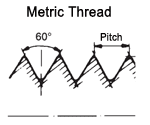
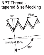
| • World-wide most commonly used type thread • Characterized by its major diameter and its pitch • Designated by the letter M followed by the value of the nominal diameter and the pitch, both expressed in millimetres and separated by the multiplication sign '×' (i.e. M12 x 1.5) | • NPT Thread = National Pipe Thread • Taper rate for all NPT threads is 1/16 • The taper on NPT threads allows them to form a seal when torqued as the flanks of the threads compress against each other, as opposed to straight thread fittings |
 |  |
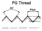
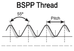
| • PG Thread = Panzer-Gewinde (also Panzer-Rohr-Gewinde) • German thread type • Depth of thread smaller than NPT or Metric, but larger flank angle | • BSPP Thread = British Standard Pipe Parallel Thread • Parallel (straight) thread with a constant diameter, denoted by the letter G • Symmetrical V-thread in which the angle between the flanks is 55° (measured in an axial plane) • One-sixth of this sharp V is truncated at the top and the bottom • Threads are rounded equally at crests and roots by circular arcs ending tangentially with the flanks • The theoretical depth of the thread is therefore 0.64 times the nominal pitch |
TORQUE RECOMMENDATIONS FOR STRAIN RELIEF FITTINGS
Torque in Inch Pounds – in lb (Newton Meters – Nm)
| Sizes | PLASTIC STRAIN RELIEF FITTINGS | METAL STRAIN RELIEF FITTINGS | ||
|---|---|---|---|---|
| DOME NUTS | THREAD AND LOCK NUTS | DOME NUTS | THREAD AND LOCK NUTS | |
| M 6 | 17.7 (2) | |||
| M 8 | 17.7-26.6 (2-3) | |||
| PG 7, M12x1.5 | 14.4 (1.62) | 22.1 (2.5) | 36.9 (4.17) | 55.3 (6.25) |
| PG 9, PG 11, M16, PG 13.5, 3/8" NPT, 1/2" NPT, M16x1.5, M20x1.5 | 22.1 (2.5) | 33.2 (3.75) | 36.9 (4.17) | 55.3 (6.25) |
| PG 16, 1/2"NPT-E | 29.5 (3.33) | 44.2 (5) | 44.2 (5) | 66.4 (7.5) |
| PG 21, PG 29, PG 36, PG 42, PG 48, 3/4"NPT, 1"NPT, 1-1/4"NPT, 1-1/2"NPT, M25x1.5, M32x1.5, M40x1.5, M50x1.5, M63x1.5 | 44.2 (5) | 66.4 (7.5) | 59 (6.67) | 88.5 (10) |
Note: Torque Specs will vary depending on the crush resistance of the cable. We recommend to determine the actual torque empirically, testing the actual cable used. The values shown above are for reference only.
Note: Nylon strain relief fittings installed in a threaded connection and exposed to elevated temperature should be retained with a sealant such as Locktite® to avoid a loose connection when temperature fluctuates.
Custom Drilling Solutions!
- Any special insert hole or profile configuration is available for a minimum order of 1,000 pieces.
- No Charge Manufacturing Fee – In 12-14 weeks or a one time Expedite Fee reducing manufacturing to 6-8 weeks.
For small quantities we suggest drilling or machining the inserts yourself
Drilling/Machining guidelines:
- We suggest drilling the frozen solid insert.
- Drill holes by using a standard high-speed steel drill bit of the proper size at approx. 2500 RPM.
- Drill holes with insert installed in Strain Relief Fitting as a fixture.
- Keep a minimum distance of 1 mm (.04 in) between holes.
- The outside holes can be located right against the lip of the strain relief body, as sufficient insert material remains between the hole and the body wall due to the design of the cord grip.
Important: Design Parameters: Cable diameter should not be less than 80% of hole diameter and the difference between hole and cable diameter should never exceed .04″ (1 mm). The Multi Cable fittings will meet Type NEMA 4x = IP65 if the design parameters are complied with.
To verify a submersible Type NEMA 6= IP68 application, the final assembly of cables and fittings must be tested by the customer or submitted at the customer’s expense to an independent test lab.
